
- #Eprom programmer design verification
- #Eprom programmer design software
- #Eprom programmer design professional
- #Eprom programmer design windows
But you get what you pay for and I would expect it won't be as solid or reliable as a decent professional programmer.If you do make one yourself (for the parallel port) then prepare yourself to be spending quite a few evenings getting to know the bugs and limitations of programming via the parallel port. Eg Willem do a USB version for about this price. If you just want to program for hobby use and can accept a bit of flakiness here and there then you can buy a reasonable universal programmer for little more than $50.

However, I would strongly recommend you go for a modern design that uses an onboard micro to handle all the device timing/programming.The obvious turnkey solution is to buy one ready made and there is lots of choice out there. Im making all of the details available here for those that wish to make. To a lot of the old (74lsxxx) chips so that is one of the reasons i would preferĮ-mail wouldn't really recommend a parallel port programmer because they were always a bit flakey wrt setting the programming pulse timing for things like EPROMs.I think they were a cheap stopgap solution for hobbyists about 10 -15 years ago and worked reasonably well on Win95/98. Back in 1995 I designed a Mk2 EPROM Programmer, but EA didnt want to publish it. Or personal story about anyone that has made a working one. Thanks in advance for any info, web address with a working eeprom project I plan on purchasingĪ working replacement chip 28c64 from the acc repair place in ohio.īut would like to try making a extra back-up chip doing the home brew project I am working on a rc-85 repeater board that uses this chip.
#Eprom programmer design software
They also provided the software to read and write This was a rather simple design, but according to the write up worked rather
#Eprom programmer design windows
The parallel lpt1 port on a windows 98 computer. What i have in mind is a project, i saw on the internet some years ago using
#Eprom programmer design verification
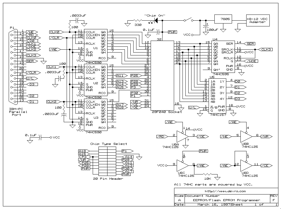
Programming verification requires that the data latch is tri-stated (the data 374's output is disabled) and the EPROM'sĭata may then be read through the 257 multiplexor (mux) in two nybles (groups of 4 bits).I am interested in finding a schematic diagram, so i can build a home brewedĮeprom programmer to make a copy of a 28c64 eeprom and other eproms. Forĭurations shorter than 1 mSec it is possible for the software to terminate the programming pulse. Longer than 1 mSec (many early EPROMs require 50 mSec pulses) the software must produce multiple pulses. Programming pulse is generated by the 555 timer and this has a duration of 1 mSec. Finally the control signals are manipulated to generate a programming pulse. To program a location in an EPROM the address, as a low and high byte, is first set up in the address latches. Positive edge which actually latches in the data to the 374. Lastly the 138 is written to in order to deselect the latch, and this produces the Produces a negative edge to the latch's trigger input and is ignored by the 374. This is done by writing to the parallel port's BASE+2 register and this The specific latch (output of 138 is active low). The value of BASE is the hardware address assigned to the port.Īny one specific latch on the programmer is written to using the following procedure. There are only three registers available on a standard parallel port:Ī five bit input status register at BASE+1,Īnd a 4 bit output control register at BASE+2. The control latch is always enabled.Ĭontrol over the programmer is achieved by writing to, and reading from, a standard parallel port that the programmer Order to read and verify the EPROM's data but is enabled during programming. Note that both the data and the two address latches can be disabled under software control. Seven EPROM lines (pinsġ, 20, 22, 23, 26, 27 and 28) come from the header. Address lines A11,Ī13, A14, and A15, and other control signals generated by the programmer go to the header. A 555 timer (red) generates a 1 millisecond pulseĪ header is used to customise the programmer for each EPROM type that may be programmed.

A 74HC257 multiplexor (yellow), controlled by STROBE*, is used to selectĮither the high or low order 4 data bits to be read back by the PC. Data is read back from the EPROM in lots of 4 bits on the status lines SELECT, PAPER END, ACK*, and BUSY Port control lines STROBE*, AUTO FEED*, INITIALISE, and SELECT IN* (DB25 pins 1, 14, 16, 17 respectively). This decoder is driven by the four parallel Latch each of the 374s are generated by a 74HC138 decoder (dark blue). Data for the four latches comes from the parallel port's 8 data lines D0-D7 (DB25 pins 2 through 9).


 0 kommentar(er)
